
SPECIFICATIONS FOR CONSTRUCTION

MATERIAL
Scoria cinder is a product of volcanic action. When the volcano erupted, the frothy, molten rock was forced over the rim. As it ran down the slope, it quickly cooled into a hard, porous rock cinder… scoria.
Scoria, when crushed, cleaned, and graded, becomes a lightweight, natural rock cinder, and comes in two colors – Red and Black.
Tracks constructed with scoria cinder from the base course to running surface provide the necessary resilience and firmness for a good track. Scoria cinders are widely used for repairing and maintaining track surfaced with other materials. Many universities, college, and high school tracks have been constructed with scoria cinders.
ADVANTAGES OF SCORIA CINDER IN TRACK CONSTRUCTION
Scoria cinder possesses certain qualities that make it particularly desirable as a material for the construction of athletic tracks. Since scoria cinders are extremely porous, the surface of the crushed material is jagged, covered with hundreds of minute spicules or projections. These tiny projections interlock when compacted, to prevent shifting and loosening. They also provide a firm hold for the binder in the running surface of the track. Because the surface of crushed scoria is uneven and jagged, it possesses cohesive qualities far superior to those of pebbles or another round, smooth particles. It is also the reason why scoria cinders can provide a firm track surface and yet maintain the desired resilience.
A certain amount of moisture is necessary for a track surface to keep it “fast.” The porosity of scoria cinder enables it to absorb large quantities of water without producing a slow, “sticky” surface. This ability to absorb moisture minimizes track care and maintenance; it substantially reduces the frequency with which the track must be wetted down and dragged.
The construction of any athletic track depends, to a great extent, upon the funds available. Specifications can be varied to fit circumstances and build a satisfactory track. A good track, with a good running surface, can be constructed at a reasonable cost using scoria cinders. Construction costs vary with the thickness of the running surface; the thickness of the base and intermediate course; the size of the track; the type and depth of excavation or fill selected; and, the drainage system.
GENERAL CONSIDERATIONS IN THE SELECTION OF AN ATHLETIC FIELD
Topography, soil conditions, rainfall, the direction of the prevailing wind, size, and accessibility are all major factors in the selection of a track site.
Size depends primarily on the sports program of the school, and the funds available. In most cases, the track is built around a field that can be used for football, baseball, or other activity.
To minimize sun glare that might handicap competitors, it is desirable to have the field run from north to south.
Protection from excessive wind must also be considered in the selection of a field site. The direction of the straightaway is determined by the prevailing wind. All races should finish on the same side.
Drainage is an important factor in the construction of a track. Drainage problems vary with the rainfall and sub-soil conditions.
The services of an architect and/or a civil engineer should be retained. These men and women are qualified to evaluate the proposed site, recommend proper construction methods, assure correct distance measurements, and overcome special engineering problems. Their assistance and advice will eliminate the possibility of costly errors.
EXCAVATION OR FILL
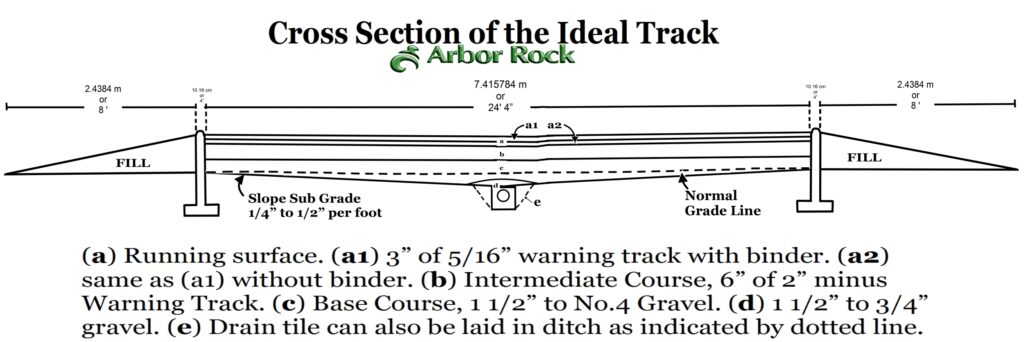
Please note: it is recommended that very little excavation be done so far as the track itself is concerned. The reason being that if the track is built on top of the ground, surface moisture from the surrounding area cannot get on the track and carry with it foreign matter that would harm the track topping, and – – – IF drainage were going to be used in the bottom of the track, this foreign matter might eventually stop up the drainage system in the track itself. In every case where the subsurface drainage is to be used in the track, the subgrade should have a slope of ¼”–½” per foot to assure adequate drainage. The drain tile can be laid down the center line of the track in a channel 10”–12” wide and 10”–12” deep, as shown in Figure 2a. In addition, the drain tile may be laid down on either side of the track. If the track is built above the ground and fill is to be used, any fill over 12” in depth should be compacted in 3” lifts with a sheeps-foot roller or compactor. Where undertrack drainage or drain tile is not going to be used, the finished subgrade should be graded so that a variation of not more than 1” over the entire area will exist. Since the top of the curb is to be exactly level, and the top of the running surface of the track is to be exactly level, it can readily be seen that time and material will be saved by grading to a true subgrade.
TRACK CONSTRUCTION
In most tracks, 6” drain tile is used. However, in areas of heavy rainfall, 8” drains are recommended. The center of the drain should be at least 9” below the normal grade level. The channel or ditch around the drain should be filled with 1½”–¾ gravel (See Figure 3). The same size gravel should be used to cover the drain to a depth of 6” and taper off beyond the edges of the ditch or channel.
CURB
Curbs have been designed both by testing laboratories and by engineering firms from 4”–6” thick, with a rounded or flat top extending not more than 2” above the running surface. After it is determined whether or not subsurface drainage will be used in the track (scuppers should be used in all cases), it should also be determined how many inches of cinders or material will be put into the actual construction of the track. Then, depending on the depth of the cinders, or the fill to be used, the curbing should be figured 2” higher than the depth of the material. If soil conditions indicate that a footing is desirable under the curbing, the footing varies from 3”–5” in depth and from 6”–12” in width. The scuppers for drainage on top of the curb should be placed every 20 feet and should measure approximately 2” in depth by 4” in width. This allows wood 2”x4” fillers to be placed in the scuppers so that if track-leveling equipment is built to work on the curbing it may be run on top of the curb without difficulty. In any event, whether the curbing is 8” above the surrounding grade level or 18” above grade level, fill must be placed on the outside of the track against the curbing, and 2” below the top of the curbing, or at scupper level, and then slope gradually away from the curbing into the infield and outfield of the track.
As has been mentioned, the base course of the track will vary from 3” –12”, depending on the type of drainage to be used or upon the funds available.
It is the opinion of most of the testing laboratories and engineers who have worked with this material that the base course, particularly in the more economical track, should consist of 5/16″”minus material, placed uniformly over the entire track area from curb to curb. It is again repeated that uniformity of surface of the subgrade will insure that extra amounts of more costly material will not be required in the topping course. If subsurface drainage is to be used in the track, then 2” minus material should be used directly over the tile and gravel using 5/16” minus material as an intermediate course.
THE RUNNING SURFACE
The running surface can vary in depth from 3” –6”, depending upon funds. When constructing a track with a 6” thick running surface, only the top 3” should be mixed with a binder (See Figure 3 a-1 and a-2). Greater depth of the running surface means more resilience and spring, faster and better drainage, and less care and maintenance.
For the topping or running surface, use 5/16” minus material. The running surface should be just above the bottom of the scuppers in the curb. If subsurface drainage in the track is used, then the running surface should be filled to the scuppers. When selecting a binder to use in the running surface, in order to get stability, it should be tested by a reputable testing laboratory for its plasticity index (“p. i.”). It is not advisable to use a binder with a p. i. of less than 10 and sized as finely as possible, but in no case have any particles in the binder larger than 1¼” screen. In determining the proportions of binder to be used, it is very important that the p. i. of the binder is known, then the lower number p. i. or the p. i. closest to 10 would feasibly start at a 40% mixture of clay in the topping; the higher the p. i. or the closer to 30–35 p. i., in most cases, it started at 15%. In any event, regardless of the p. i. of the clay, at least three test plots should be made within the range of 15%–40% clay in the mixture. In mixing the binder in with the actual running surface, or the top 3” of the track, several methods have been used successfully:
The most recent track, installed in Denver, Colorado, used the following method: They determined the amount of water they wanted in the mix, then put the correct amount of water in a Ready-Mix truck, adding their binder to the water in the Ready-Mix truck and letting it slosh around in the mixer for approximately 10 minutes, thereby forming a slurry out of the binder and water. Then they added the proper proportion of scoria cinders to the clay and water mixture, and let this mix on the way to the track site from the batch plant. As they dumped the mixture or topping out of the Ready-Mix truck, they had a vibrating screed running along the curbing to spread the entire mixture evenly over the surface of the track.
Another method that has been used, and is highly successful, is to spread the topping cinders evenly ever the entire track, then spread the desired amount of binder over the entire track. In spreading the binder, it is suggested that a fertilizer spreader be used, or in the case where one might be available, a sand or chip spreader could be used. In any event, the clay should be very carefully metered to the proper proportions over the entire topping.
It is the opinion of the testing laboratories and civil engineers (who have been consulted extensively and who have had actual experience with the building of the various type tracks) that the more economical type track, in the long run, would be fully as good as the more elaborate track or the more expensive track. This is due to the fact that after a period of 15 years, it is highly probable that the more expensive track, with all of the elaborate drainage systems, etc., could be no better than the more economical track, since in many cases, the drainage becomes clogged due to foreign material falling onto the track out of the air. Further, in many cases, due to heavy traffic around and on the track, the base and intermediate courses become so packed that drainage is slow. A very simple and economical undertrack drainage system can be specified and in most cases will serve the purpose adequately.
The intent of this discussion is to furnish a basis for engineers and architects to use as an aid in building and designing a better and more economical athletic track. Therefore, we pass on to you the following points and suggestions (authority of various testing laboratories in a large area in the middle part of the United States and engineers from the same area, also some of the best track coaches, many of whom have had as many as 35 years of experience with track construction and training): the track should always be built above surrounding grade level so that the curbing built up to contain the track may dam off all surface moisture from the track. Concrete curbing was economically possible, should be used because of its durability. Scuppers, as previously explained, should be placed in the curbing regardless of whether undertrack drainage is used or not, so that excess moisture on top of the track may be drained off through the scuppers. The barest minimum of track cinders to be used should never be under 5”; with only the top 2½” mixed with binder. It is better to have 6” of cinders with the top 3” mixed with binder. This is true, regardless of whether undertrack drainage is used or not, and regardless of whether there are base course and intermediate course below the actual topping cinder or not. The reasoning behind this being that if, for instance, 5/16” minus crusher run is used in the top 5”-6” with only 2½”-3” mixed with binder, in order to renew the topping after a period of years it is only necessary to use a disc or soil pulverizer and going deep enough with said equipment, 4”-5”-6” to bring up some of the cinders below the actual topping to renew the topping. In mixing the topping, if it is economically possible, always use the Ready-Mix truck method. In other cases, it is good to dampen the cinder the night before, applying the binder to be used evenly over the entire track, since in doing this, segregation of the binder from the cinder is largely eliminated. In this connection, it is important to note that in working with cinders we are working with sieve sizes of 1/8th of an inch to 1/50th – 1/100th of an inch. In working with a binder material, we should be working with the bulk of the binder in micron sizes (powder). It necessarily follows that segregation can occur, and in most cases does occur, if the binder and cinder were mixed at a location other than the track site or on the track itself. One way to eliminate segregation is to use the Ready-Mix truck method. Another way would be to attempt to keep the material damp from the time of mixing until the application, thereby reducing the probability of segregation, however not eliminating it. Again, at the suggestion of testing laboratories, coaches and engineers, it is suggested that 5/16” minus crusher run be used as a topping method.
Many tracks have been built using 5/16” minus crusher runs as a base and as a topping aggregate, particularly where only 5”-6” of material is to be used in the entire track.
2” minus crusher run, black – wt. pcy. Approx. 1600 lbs.
2” minus crusher run, red – wt. pcy. Approx. 1800 lbs.
5/16” minus crusher run – wt. pcy. Approx. 1800 lbs.
These weights will naturally vary due to absorption of moisture. For instance, 2” minus and 5/16” minus crusher run weigh as little as 1500 lbs. per cubic yard. For estimating purposes it is advised that the higher ‘per cubic yard’ figure be used. Freight rates to all points of the United States will be furnished upon request. Arbor Rock will be happy to work with you on initial track planning and furnish estimates of quantities and cost of scoria material.